Please Follow the Instructions for your App and your Controller
RDR Lighting Manual
| JellyFish Designer App | JellyFishP2 App | JellyFish App | |
|---|---|---|---|
| Controller | Black P2 | Black P2 | White P1 |
| Solid Colors | ✓ | ✓ | ✓ |
| Preset Patterns | ✓ | ✓ | ✓ |
| Preset Accent Lighting | ✓ | ✓ | ✓ |
| Pause Patterns | ✓ | ✓ | ✓ |
| Slow Patterns | ✓ | ✓ | |
| Dimmable | ✓ | ✓ | |
| Single Nightly Timer | ✓ | ✓ | |
| Multiple Nightly Timers | ✓ | ||
| Weekly Timers | ✓ | ||
| Calendar Events for Holidays | ✓ | ||
| Create Custom Patterns | ✓ | ||
| Create Custom Accent Lighting | ✓ | ||
| Individually Addressable Lights | ✓ | ||
| Zoning | ✓ |
Quick Start Guide: JellyFish Designer App
Updating a Black P2 Controller from the JellyFishP2 App to the JellyFish Designer App
- Download the JellyFish Designer app from your app store
- Make sure your black Pro2 controller is turned on (use the switch on the left side)
- Make sure the controller is connected to your home WiFi
- Test this by connecting your phone to your home WiFi and controlling your lights with the old JellyFishP2 app
- If your controller isn’t connected to WiFi, you’ll need to move your controller into an area that has WiFi because a controller needs to be connected to WiFi to update
- Open the JellyFish Designer app
- When the app opens, it will automatically scan for version 1 firmware and ask if you want it to update to JellyFish Designer (the latest version)
- If it doesn’t ask you to update the first time, try killing the JellyFish Designer app, when it restarts it will scan for version 1 firmware again and ask to update
- Press “Yes”
- It will take a while to update
- Once you update your controller, the JellyFishP2 App can no longer control the controller
- Note: We have not transferred the code for the LED strip above the LCD screen on the controller, so it is normal for now for it to stay on and not display the pattern playing
List Tab in the Menu: All Saved Patterns & Accents Sorted by Category
- Select the zone:
- Press ▼ next to “All Zones” to select the zone you’d like to turn on
- By default, your system is set to a zone called “All Lights”
- If you have created your own zones, they will show up here
- To turn on a zone, toggle it to blue. To turn off a zone, toggle it to grey
- To play a new pattern on a zone, make sure the zone is both toggled on/blue and the box to the right is selected with a ✓
- If the zone is toggled on/blue but the box to the right is not selected, you are not changing what is being displayed for that zone (it will stay the same)
- If your system only has the “All Lights” zone configured, turn it on/blue and select the box to the right with a ✓
- Press ▼ next to “All Zones” to select the zone you’d like to turn on
- Press the ∨ on the category to display the list of corresponding patterns or accents
- Press the play button to the right of the desired program
- After a pattern starts playing, the pattern can be modified and resaved
- To modify an existing pattern or accent:
- Play the pattern you’d like to modify
- Press the “adjust” icon to the left of the play button to open the adjust page
- Press “Save” and rename it
- You can also get to the adjust page by pressing “pattern” if you want to adjust a pattern or “accent” if you want to adjust an accent in the lower menu bar while the lights are on the pattern or accent you’d like to adjust
- To delete patterns:
- Press the ⋮
- Press “Delete Pattern”
Pattern Tab in the Menu: Create New Patterns
*Note* – This video can be used to help create new programs using any pattern
- Select the zone:
- Press ▼ next to “All Zones” to select the zone you’d like to turn on
- By default, your system is set to a zone called “All Lights”
- If you have created your own zones, they will show up here
- To turn on a zone, toggle it to blue. To turn off a zone, toggle it to grey
- To play a new pattern on a zone, make sure the zone is both toggled on/blue and the box to the right is selected with a ✓
- If the zone is toggled on/blue but the box to the right is not selected, you are not changing what is being displayed for that zone (it will stay the same)
- If your system only has the “All Lights” zone configured, turn it on/blue and select the box to the right with a ✓
- Press ▼ next to “All Zones” to select the zone you’d like to turn on
- Select a pattern mode:
- Press the ▼ next to the pattern mode
- Color – Solid
- Chase – Lights moving in sequence
- Paint – Solid color that changes color by stacking 1 light at a time back and forth
- Stacker – Solid color that chances color by one light tracing through and stacking to the other side (zones have to be set up to use this)
- Sequence – All lights flashing through the same colors in the pattern at the same time
- Multi-Paint – Solid color that changes color by spreading out from a point
- Select the number of colors in the pattern:
- Press the – and + next to “# Colors”
- For a uniform solid color, set the “# Colors” to “1”
- Change the colors in the pattern
- Press the color you want to change
- A selected color will become a circle, meaning you can change it
- An unselected color is a square and must be selected to change
- Using the rainbow sliding bar, choose a new color
- The second sliding bar will adjust the shade/intensity of the color
- Press the color you want to change
- To save a color:
- Press and hold a square under “Custom” while the color you want to be saved is playing
- Press the ▼ next to the pattern mode
- “Adjust” tab in the upper menu
- Color Transforms
- Must have two or more colors selected in the pattern
- There are different color transforms available for different pattern modes (not all color transforms are available for every pattern mode)
- Select a color transform by pressing the ▼ next to “No Color Transform”
- No Color Transforms – Doesn’t do any color transforms
- Repeat – Changes the amount of lights that are each color in a row
- If the repeat number is 3, there will be 3 of each color in a row
- Progression – How many colors will show between the transition from one color to another
- If the progression number set is 3, the lights change color in 3 steps from red to blue (red, dark pink, light pink, white, reverse)
- Fade – Changes the brightness intensity from color to color
- If the fade number is 3, the lights change brightness in 3 steps from color to color (off, half on, fully on, half on, off, change color, repeat
- Skip – Makes the pattern skip lights, instead of changing every light
- If the skip number is 3, every 3rd light will move the pattern
- Fill with Black – Turns lights off between each color
- If the fill with black number is 3, there will be 3 lights turned off between each color
- Direction – Changes the direction of the pattern
- # of LED’s – A pattern playing in multiple places at once
- If the # of LED’s is 2, the lights will be playing 1 pattern in 2 places
- Effects
- No Effect – No effect
- Twinkle – Flashes 1 white light randomly
- The slider next to “Twinkle” changes the frequency
- Lighting – Flashes 3 white lights randomly
- The slider next to “Lighting” changes the frequency
- Speed – Use the slider to change the speed
- Brightness – Use the slider to change the brightness
- Red – Use the slider to take out or put in red into the pattern
- Green – Use the slider to take out or put in green into the pattern
- Blue – Use the slider to take out or put in blue into the pattern
- Color Transforms
- “Save”
- Rename the pattern created
- Choose the category it will be under on the “List” page or create a new category
- *Note* – Only saved patterns can be recalled by timer or calendar events, or recalled spontaneously
Accent Tab in the Menu: Create New Accent Lighting Patterns
- Select the zone:
- *Note* – In order for the “Accent” mode to work properly, the zones need to be set up with the correct number of lights on each zone (skip to zone section for how to)
- If there are 113 lights on the front of your home, the zone needs to be 113 lights
- Press ▼ next to “All Zones” to select the zone you’d like to turn on
- By default, your system is set to a zone called “All Lights”
- If you have created your own zones, they will show up here
- To turn on a zone, toggle it to blue. To turn off a zone, toggle it to grey
- To play a new pattern on a zone, make sure the zone is both toggled on/blue and the box to the right is selected with a ✓
- If the zone is toggled on/blue but the box to the right is not selected, you are not changing what is being displayed for that zone (it will stay the same)
- If your system only has the “All Lights” zone configured, turn it on/blue and select the box to the right with a ✓
- *Note* – Only 1 zone can be toggled on/blue and only the box to the right of that zone can be selected with a ✓ while creating an accent lighting pattern
- *Note* – If a zone is modified after an Accent is created, the Accent may not display correctly
- *Note* – If an Accent is created and the name of the zone changes after the Accent has been created, the Accent will no longer work
- *Note* – In order for the “Accent” mode to work properly, the zones need to be set up with the correct number of lights on each zone (skip to zone section for how to)
- Choose what lights are on
- Pressing the – and + will move a white blinking light across the roofline showing which light is “active” and be turned on or off
- If “Set” is pressed, this “active” light becomes the “accent” color. A light that was not “set” it will become the background color
- *Note* – Each light is recognized by the controller as a number (the 1st light is 1, the 2nd light is 2, and so on.) The display on the app shows which lights are “accent” lights by their “number”
- Choose the colors
- Click the box under “Accent” to the right of “Colors:”
- Choose what color you want with the sliders
- Press “Done”
- If you want all accent lights to be that color
- Press “Set All Color”
- If you only want some of the accent lights that color
- Select the lights you want to set that color (it will become a ◯)
- Press “Set”
- Keep selecting and setting all the lights you want that color
- If you want to have the rest of the lights that weren’t chosen or all the “background” lights to be a certain color
- Click the box under “Background” to the right of “Colors:”
- Select the color you want
- Leave black if you want the rest of the lights to be off
- Click the box under “Background” to the right of “Colors:”
- This can also be done when creating a new accent lighting pattern
- Start with none of the “accent” lights defined
- With the “Active” light blinking on light #1, change the “Accent” color to the desired color by pressing the box under “Accent”
- Press “Done” once you choose your color
- Press the “Set” button
- Light #2 is now the active color as it is blinking
- Change the “Accent” color again by pressing the “Accent” color box and selecting a new color
- Press “Done” to save the color
- Press “Set”
- This process can be followed for every light in the zone to create a completely custom sequence
- Click the box under “Accent” to the right of “Colors:”
- *Note* – The default white is a cool white, if you want a warm white:
- Select the “Pattern” page
- Select the Drop Down Pattern Mode of “Color”
- Select yellow underneath the Primary Colors
- Now Adjust the brightness slider toward the white end and you’ll get off-white colors
- To save this color for future use, press and hold one of the custom button squares for a few seconds, and the will save the current color to the custom color square
- The color that was there will be replaced with the color being displayed on the LED’s and that color will be available when doing an “Accent”
- -OR-
- Sometimes it can be difficult in getting the color you want, and sometimes it’s easier to start with a color that is close
- Select “List” page
- Select the “Warm Cool” category down arrow or the “Colors” category down arrow
- Select the color you want
- Select the “Pattern” page
- Then change the Color selector and the Brightness selector until you have arrived at the color you want
- If you want to save this color to the custom palette, press and hold the box, and after 2 seconds, the color being viewed will be saved in that color box. This color will be available doing an Accent or a Pattern
- The color that was there will be replaced with the color being displayed on the LED’s and that color will be available when doing an “Accent”
- Delete an “accent” light
- To select a light, click on the square of the light you want to delete (it will become a ◯)
- Click “Clear”
- Delete all “accent” lights
- Press “Clear All”
- “Adjust” tab in the upper menu
- Effects
- No Effect – No effect
- Twinkle – Flashes 1 white light randomly
- The slider next to “Twinkle” changes the frequency
- Lighting – Flashes 3 white lights randomly
- The slider next to “Lighting” changes the frequency
- Brightness – Use the slider to change the brightness
- Red – Use the slider to take out or put in red into the pattern
- Green – Use the slider to take out or put in green into the pattern
- Blue – Use the slider to take out or put in blue into the pattern
- “Save”
- Rename the pattern created
- Choose the category it will be under on the “List” page or create a new category
- *Note* – Only saved patterns can be recalled by timer or calendar events, or recalled spontaneously
- Effects
Schedule Tab in the Menu: Daily Timers and Calendar Events
- To save a daily timer
- Select “Daily” at the top of the page
- Press “+ Event” near the top right corner
- Press “Select Pattern” (Opens all of the saved patterns to display)
- *Note* – If there is not a saved pattern to choose from, one can be created using the “Pattern” page or the “Accent” page
- Select the zone for which this timer applies by clicking the box which will make a ✓
- Select the days on which this timer should be active and working
- Select the start and stop time
- To set a specific time:
- Slide to start and use the sliders to make the start time
- Slide to stop and use the sliders to make the stop time
- To use sunrise or sunset
- Slide to sunset or sunrise
- An offset from sunset or sunrise can be selected
- The offset is the number of minutes or hours, before or after sunrise or sunset that the event should start or stop
- + is time after sunset/sunrise
- – is time before sunset/sunrise
- To set a specific time:
- Press “Save”
- After the event is saved, it will show up in the daily timer list
- To save a calendar event
- Press the “Calendar” button at the top of the page
- Press “+ Event” near the top right corner
- Press “Select Pattern” (Opens all of the saved patterns to display)
- *Note* – If there is not a saved pattern to choose from, one can be created using the “Pattern” page or the “Accent” page
- Select the zone for which this timer applies by clicking the box which will make a ✓
- Press the “Begin Date” button and choose a date
- Press “OK”
- Press the “End Date” button and choose a date
- Press “OK”
- Select the start and stop time
- To set a specific time:
- Slide to start and use the sliders to make the start time
- Slide to stop and use the sliders to make the stop time
- To use sunrise or sunset
- Slide to sunset or sunrise
- An offset from sunset or sunrise can be selected
- The offset is the number of minutes or hours, before or after sunrise or sunset that the event should start or stop
- + is time after sunset/sunrise
- – is time before sunset/sunrise
- To set a specific time:
- Press “Save”
- After the event is saved, it will show up in the daily timer list
Setup Tab in the Menu: Zones, Controller, Settings, WiFi Setup, Updates, Etc
*Note* –A zone is a section of lights you group together logically, for example the front and backyard. Defining different zones for your home allows the ability to only turn on certain sections of lights, or to have different patterns on different parts of their home.
*Note* – When setting up a zone, you have to choose which ports were used to power that section, so here is a description of what a the ports are. All lights are hard wired to your controller. Multiple wires may have been used to connect your lights to your controller. A JellyFish Pro 2 controller has up to 4 ports, therefore, up to 4 wires may be connecting your lights to your controller.
*Note* – A zone of lights you create can include part of the lights connected to a port, all of the lights connected to a port, or a group of lights spanning multiple ports. In the JellyFish Designer app, patterns are run on zones, not on ports.
*Note* – By default, your controller will be set up to have only one zone called “All Lights”. The “All Lights” zone will mirror the information on port 1 to ports 2, 3, and 4. Also, by default, your controller assumes that each port is connected to 512 lights because each port can potentially communicate with up to 512 lights. As a side note, a controller can not power up that many lights without an auxiliary power supply, but a single port can communicate with 512 lights nevertheless.
*Note* – A section of lights can only be a member of ONE zone.
*Note* – If a light is not defined in any zone, it will always be off.
- Zones (Create or modify a zone)
- Delete the “All Lights” zone by pressing ⋮ to the right of the zone name and by selecting “Delete Zone”
- We are deleting this because each light can only be assigned to 1 zone
- Please note that ⋮ needs to be pressed before the zone is expanded. If the dots are pressed after the zone is expanded, the only option available is to add a port.
- Press “+ Add Zone”
- The default name after pressing “+ Add Zone” is “Zone”
- If there are multiple named “Zone” it will add a number after it (Zone1)
- The default name after pressing “+ Add Zone” is “Zone”
- Be outside looking at the lights while setting up zones
- It will automatically open up the port settings
- If editing, press ? to the right of the zone you’d like to edit
- Press “Port:1”
- Save the “Start” and “End Position” for the zone
- Select port number 1
- The numbers next to “Ports” are which port was used to power each strand of lights. The installers normally use port 1 first
- The port you are editing will be Ⓞ
- Press – and + to the right of “End Position” to set which lights you want in that zone
- This will move the blue light and add more white lights
- All of your lights should be white except for the 1st and last light in the zone
- If two ports are used in the zone you want to create
- While in the expanded zone menu, press ⋯ “Add Port” and repeat the above until you select all the lights you wish to have in the zone
- Press ∧ once you have the lights in the zone all selected to save
- Select port number 1
- “Reverse Direction” will make the lights in that zone flow the other way
-
To rename the zone click out of the zone then 3 vertical dots when closed out of the zone and select rename
- A zone of lights should be a logical name like “Front Yard”, “Side Yard”, or “Patio”
- To make sure you have your zone set up how you want it, you can test it
- Press ⋮ to the right of the zone name when the zone is not expanded
- Press “Start test”
- This will turn all lights in the selected port on red and will have one green light tracing through to show the direction
- Press ⋮ to the right of the zone name when the zone is not expanded and press “End Test”
- Delete the “All Lights” zone by pressing ⋮ to the right of the zone name and by selecting “Delete Zone”
- Controller
-
Multiple controllers can be managed here
-
- Config
- Press the ▼ under “Time Zone” to change your time zone
- Press the ▼ under “Location” to change your location
- Press “Set” to save
- Controller will reboot
- “Set Default Zone List” will restore the default zone list “All Lights” (this will delete the zones you created)
- “Restore Zone List” will restore to the previous zone list
- About
- “Find Controller” searches for lighting controllers
- “WiFi Setup” walks you through the setup wizard
- Helpful if you get new WiFi
- “Update Controller Firmware”
- Update JellyFish Designer Controller
- JF Designer Tutorials will take you to a page with all of our tutorial videos
Quick Start Guide: JellyFish P2 App
Pairing your Controller to WiFi – Setup Wizard
**Only do this if your installers didn’t or you got a new WiFi setup**
- Make sure the controller is turned on (use the switch on the left side)
- Connect your smart device to the JellyFish WiFi
- Open your smart device’s WiFi settings & turn on WiFi (If on, turn off & then on)
- Password is bigfish10
- Once connected to the WiFi press “set-up wizard” and follow the instructions on the app
- You will have to log into your WiFi and link it
- This may take a few tries – try killing the app and reopening if needed
- If the WiFi is not discoverable from the garage that may mean a WiFi extender is needed
- If you see “your network name_ JF” in your list of available networks on your phone you have a successful pairing
- If you ever reset your controller you will need to go through the setup wizard again on your device to connect to the controller again
How to Turn on a Lighting Scene
- As a program
- Press the Programs Icon
 to access the programs
 - Touch the program icon to choose the lighting program you want to display
- If desired, modify the colors, brightness, or speed of the program
- Press the Programs Icon
- As a solid color
- Go to the solid colors page
- Touch the color to select a solid color
- If desired, modify the brightness of the color by sliding your finger along the vertical bar on the right
Timer Setup in App – Short Version
- Go to the “Settings” page of the mobile app and press “Controller Settings”
- If “Controller Settings” isn’t visible press “Search for Controller”
- Use “Timer Setup” to set the time to turn lights on and off daily
- The controller must be connected to your local network to use “sunset” and “sunrise” options
- The “+” means offset after sunset/sunrise. The “-” means offset before sunset/sunrise
- Turn on the lights with the program or color you want to use when the timer is on then press “Set”
- Change “Timer Enable (on/off)” to on
Suggested Holiday Presets
| Christmas | 1, 5, 7, 8, 24, 28, 44 |
| Halloween | 28, 29, 37, 48, 54, 56, 58 |
| Patriotic Holidays | 11, 14, 19, 63 |
| Easter | 21, 45, 47, 55 |
| Valentine’s Day | 1, 2, 52, 53 |
| Saint Patrick’s Day | 13 |
Preset Directory
| Christmas | 1, 5, 7, 8, 24, 28, 44 |
| Halloween | 28, 29, 37, 48, 54, 56, 58 |
| Patriotic Holidays | 11, 14, 19, 63 |
| Easter | 21, 45, 47, 55 |
| Valentine’s Day | 1, 2, 52, 53 |
| Saint Patrick’s Day | 13 |
Preset Directory
| Program 1 | Alternating red and white |
| Program 2 | Alternating pink and white |
| Program 3 | Alternating yellow and white |
| Program 4 | Alternating lime green and white |
| Program 5 | Alternating green and white |
| Program 6 | Alternating purple and white |
| Program 7 | Alternating blue and white |
| Program 8 | Alternating red and green |
| Program 9 | Alternating lime green and pink |
| Program 10 | Alternating blue and orange |
| Program 11 | Alternating red and blue |
| Program 12 | Alternating blue and green |
| Program 13 | Alternating yellow and green |
| Program 14 | Flashing red, white, and blue in sections |
| Program 15 | Every 4th light on |
| Program 16 | Every 6th light on |
| Program 17 | Every 8th light on |
| Program 18 | All lights on bright white |
| Program 19 | Flashes red, white, and blue |
| Program 20 | Alternating green and purple with 2 off lights in between |
| Program 21 | Alternating purple,blue, and green with 2 off lights in between |
| Program 22 | Blending through colors of the rainbow |
| Program 23 | Blending through blue, purple, orange, and pink |
| Program 24 | Alternating red, green, and white |
| Program 25 | Chases through rainbow |
| Program 26 | Chases through purple, green, and blue |
| Program 27 | Chases through orange, yellow, and white |
| Program 28 | Alternating red, blue, yellow, and green |
| Program 29 | Chases through green, orange, and purple |
| Program 30 | Alternating blue and orange |
| Program 31 | Alternating yellow, blue, and red |
| Program 32 | Chases red, white, and blue |
| Program 33 | Chases blue, purple, orange, yellow, and green |
| Program 34 | Chases peach, pink, yellow, orange, green, purple, and blue |
| Program 35 | Flashes yellow, orange, and white with twinkling |
| Program 36 | Flashes purple, pink, green, gold, orange, and blue with twinkling |
| Program 37 | Flashes orange and purple with twinkling |
| Program 38 | Flashes red, gold, and orange with twinkling |
| Program 39 | Flashes green, blue, and orange with twinkling |
| Program 40 | Flashes orange, yellow, and pink with twinkling |
| Program 41 | Flashes pink and blue with twinkling |
| Program 42 | Flashes purple and green in sections |
| Program 43 | Blended chasing rainbow |
| Program 44 | Blended chasing rainbow |
| Program 45 | Blended chasing pink, purple, and blue |
| Program 46 | Blended chasing pastel rainbow |
To Make an Off-White Color within the Accent Lighting Preset
- Press the program with the spacing you like
- Press the settings gear in the corner
- Match the red, blue, green combination below and adjust from there
How to Tell if you’re Connected to WiFi
- Controller is connected if there is an asterisk on the top right of the controller screen
- App or controller is not connected to WiFi or controller if there is a in the top right corner appears in the JellyFishP2 app
Finding Out what Firmware is Installed
- On the app click settings and then select
- ”Controller Settings” and select “Update Firmware”
- If you do not see “Controller Settings” it means the controller is not connected to WiFi
- You can look on the controller screen and the firmware version will be there
- If the firmware version is not on the screen, you have to look at the JellyFishP2 app:
- Open the app
- Verify proper controller function by switching the lighting program and confirm it matches the controller
- Your device has to be connected to the controller to verify firmware version
- Click on the “Settings” at the bottom of the app
- Write down the Controller IP address which is at the top right (ie: 192.168.1.226)
- Open up a new browser and type in that IP address into the search bar
- Press enter
- This allows you to log into the controller which will have the current version (ie: 0.1.5-r.32)
- Any version below 0.1.5-r.32 will have the firmware glitch, but after won’t
- You can click to try beta versions if available
Updating the Firmware
- Open the app
- Click “Settings”
- Click ”Controller Settings”
- If “Controller Settings” button is not there, then you need to connect to controller WiFi
- Click ”Update Firmware”
- Wait until the controller is updated, this will take a few minutes
 ”Update Firmware”
Timer Setup in App – Long Version
- Assure that you have the current version of the app, to check:
- iPhone: Press the CONTACT button
- The current iPhone version is 1.3.6
- Android: Press the CONTACT button
- The current Android Version is 1.3.5
- iPhone: Press the CONTACT
- Find your installed controller
- Assure that the TIME and DATE on the controller are correct
- If the time and date are not correct, set the correct time and date
- Open your JellyFishP2 app
- If there is a black triangle on the top right of the page, it means the phone is not connected to the controller, to connect:
- Touch the “settings” icon at the bottom of the page Apple: Android:
- Press “Search Lighting Controllers”
- You must be connected to the WiFi that your controller is
- Touch the “settings” icon at the bottom of the page Apple:
- If there is a
- Set up a lighting scene with a program or a solid color. (Note, a lighting scene must be active on the controller so the controller can save the current lighting scene to the timer)
- You can modify a program by touching the gear on the top right of the programs screen. You are able to adjust program speed, brightness, or adjust colors in this setting. Once the program is modified, you can go to the timer settings page and when you hit “set” the timer will come on and run the adjusted program.
- Touch the “settings” icon on the bottom of the page
- Apple: Android:
- Apple:
- Touch the CONTROLLER SETTINGS button
- At the top of the page it now says “Controller Settings”
- Make sure the location is correct
- Make sure the Time Zone is correct
- Go down to TIMER SETUP – touch the arrow
- Set the ON TIME
- Select either the On Time or Sunset with an offset. Change the time or offset by rolling your finger up and down.
- Set the Off TIME
- Select either the Off TIME or Sunrise with an offset. Change the time or offset by rolling your finger up and down.
- The “+” means offset after sunset/sunrise. The “-” means offset before sunset/sunrise
- Press SAVE on the “timer set up” page to save the settings.
- Now the Controller Settings page should be visible.
- Save the current lighting scene by pressing SET.
- Go to TIMER ENABLE – if it is already ON, turn it OFF, and immediately turn it back ON again. If the TIMER ENABLE is OFF, turn it ON
- Click Solid Colors or Programs
- In the top left corner your lights will be on tap the button and it will turn them off
 Android:
 button
 Solid Colors or Programs
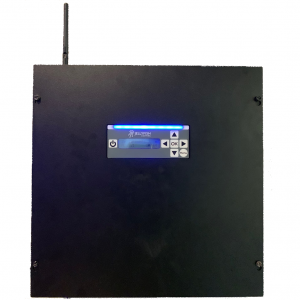
Operating Manual: Black P2 Controller
Controlling your Lights from the Control Box
- Press the power button on the JellyFish-Pro2 Controller to turn the lights on
- The program can be changed by pressing the left and right arrows
- The top line of the display will say “Programs” followed by a number – this is the program the lights are displaying
- Press OK to change the bottom line display text from “Speed” to “Brightness”
- Use the up and down arrows to change the program speed or brightness
- Press Menu to change the display between “Programs” and “Colors”
- Colors is used to display solid light colors- when the top line of the display starts with “Colors” use the left and right arrows to change the light color
- The “R000 G000 B000” on the bottom line show what percentages of Red, Green, and Blue are being displayed in the current color
- Holding a left or right arrow will make the lights cycle through the colors faster
- The up and down arrows will adjust the color brightness
- Press and release power quickly to pause a currently running program
- Press power for 4 seconds to turn the lights off – the fan will shut off 1 second after the lights turn off
- If the lights are off, pressing power will turn the lights on to the last program or color before the lights were turned off
Setting the Date and Time
- If the Pro2 Controller is connected to your home network the time will not need to be set manually
- Press and hold the “Menu” button until the display shows “>Setup” on the top line
- “Date” will be displayed on the next line. If it isn’t, press the Down or Up arrow until it is displayed
- The “Time” setting can be displayed by using the Down or Up arrows
- Press the OK button
- An Asterisk (*) will appear before the field (month, day, year, hours or minutes) you are setting
- Use the right and left arrows to change the entry
- Once a time parameter is correct press OK to save. Pressing Menu will discard the setting
- Once all entries are completed Press Menu until the display is back to “Programs”
Turn the JellyFish WiFi (SSID) Off
- Press and hold the “Menu” button on the touch pad located on the controller to open the setup menu
- Press the down arrow button three times until the display says “WiFi”
- Press “OK”
- Press the down arrow button until you see “ON (OK Changes)”
- Press “OK”
Turn the JellyFish WiFi (SSID) On
- Press and hold the “Menu” button on the touch pad located on the controller to open the setup menu
- Press the down arrow button three times until the display says “WiFi”
- Press “OK”
- Press the down arrow button until you see “Off (OK Changes)”
- Press “OK”
Troubleshooting Guide: Black Pro 2 Controller/JellyFishP2 App
WiFi Connection
Network is not operating correctly
- Turn off the network and turn it back on
- Turn off any access points and turn them back on
Home Network is 5.8 Ghz
- Run and Cat 5/Cat 6 from the router to the controller
- Add a network extender
Controller and Home Network are too Far Apart and Can’t Communicate
- Add a range extender
- Add a cable
New Router or New Password on Router – Need to Reset WiFi on the P2 Controller
- Hold down “Menu” on the controller
- Arrow down 3 times until it says “WIFI”
- Click “OK” to reset, this will take a minute
- Click “Menu”
- If the asterisk on the top right of the controller screen is gone then it has reset, if it is still there it hasn’t reset
- Open the JellyFishP2 App
- On the top right you will see meaning it is not connected to the WiFi correctly
- Open your smart device’s WiFi settings
- Search and click on the network called “JellyFish”
- The JellyFish network password is bigfish10
- Go back to the JellyFishP2 App
- Click on the “Setup Wizard”
- Click “Continue” 3 times and it will search for networks available
- If you’re kicked out the first time, reopen the app & click continue 3 times again
- Scroll to your network, it lists the strongest WiFi signal first
- Type your WiFi password in (new one if you changed it on your router)
- Click configure WiFi
- If connected, an asterisk will appear on the top right of your controller screen
- This will need to be done again if you change your network password, get a new router, or reset your controller
Network Name isn’t in the Setup Wizard or it is but won’t Connect
- If your network is 5.8 Ghz, add a network extender which will talk to the 5.8 Ghz network and to the controller’s 2.4 Ghz network or to the controller through a cat 5 cable
- If that doesn’t work, run a network cable from the controller to the router
- If your network is 2.4 Ghz, then your network may not be operating correctly
- Reboot your network and all access points
- If that doesn’t work, run a network cable from the controller to the router
- If that doesn’t work, it could be the JellyFish controller
- Reboot the controller by turning the switch(on the left bottom side of controller) off and then on.
The Controller won’t Connect Even Though it’s Directly Connected with a Network Cable Unless the Controller is Unplugged and Plugged Back In
- Make sure the link light is on, located at the base of the network cable connection on the controller.
- If there is not a link light on, the cable isn’t connected properly to the network router or switch. Try a new cable or new terminals.
WiFi Extender
Follow this video except plug the extender in an outlet near your JellyFish controller and hard wire it with an Ethernet cable.
- Micro Center or Home Depot has them
- Also purchase an Ethernet cable
- Tp-link AC1200 or AC750 WiFi Range Extender
- Plug into an outlet near the WiFi router
- Wait until the power light turns solid
- Connect to the WiFi extenders WiFi on either a computer or a phone
- Open the settings and connect to WiFi as usual
- Open a browser and go to www.tplinkrepeater.net
- Create a password to log in (just for you to access WiFi extender in the future)
- The extender will scan for networks
- Choose the network you’d like your JellyFish controller paired to
- ALWAYS select the 2.4 GHz, DON’T enter password for 5 GHz WiFi so press skip because the controller can only connect to 2.4 GHz
- Enter WiFi password and continue
- Click next
- Wait until it gets to 100% paired
- Then relocate the extender to an outlet near the controller
- Hard wire the extender and the JellyFish controller with an Ethernet cable
- To connect the controller, go through the setup wizard (see first section)
Ethernet Over Power – If WiFi Extender Didn’t Work
- Micro Center or Home Depot has them
- Tp-link AV600 Powerline (Starter Kit TL-PA4010 KIT)
- Plug 1 directly into a wall outlet (no surge protector or other adapter) by the controller. Plug the second one into the wall right by the router to hard wire to the router
- Once the router is hard wired and the button is clicked, click the button on the device by the controller
- Once all three lights are on then hard wired it into the controller
- Connect phone to network and press “Search Lighting Controllers”
- If hard wiring, you can be connected to the 2.4 GHz or 5.0 GHz network
- If wireless, you have to connect to the 2.4 GHz network
Controller
Controller is not Operating Correctly
- Turn the controller off and turn it back on with the power button
- If that doesn’t work try rebooting by turning off and on the switch on the (left) side bottom of the controller.
Controller Keeps Rebooting
- Needs to be repaired by a JellyFish Tech
Controller Update Fails
- Causes:
- Internet is NOT accessible to the controller through the network
- The controller has an error keeping it from updating
- First verify that these three following conditions exist
- The controller has a good network and internet connection.
- A firmware version of 18r13 or older
- AND after a firmware update button press, the controller continually shows “Controller Updating” and it never stops
- To fix this issue, do the following:
- Download the Jellyfish Updater app on the Apple Store (This is currently not available for the droid operating system)
- Turn the controller on and make sure it is connected to the local network to the internet
- Open the “Jellyfish Updater” App
- The app will scan for the controller connect to the controller, and start the update
Control4 is Preventing the Controller from Connecting to WiFi
- Hook up a WiFi extender to the router
- Do not continue with setup for the extender, just connect the controller to the extender directly to surpass Control4
Lights
Lights on House & the Controller’s LED Light Strip are Flickering
- Easiest to identify on program 17
- All you have to do is update the firmware
- Firmware version below 0.1.5-r.32 may glitch and need to be updated
Lights on House are Flickering, but the Controller’s LED Light Strip is Not
- Run some tests to see what the issue is:
- Go to the point where the lights start flickering
- Replace the last light that’s working and the first light that isn’t
- If that works, you are good to go
- If that doesn’t work, if there is more than ~70 feet of wire to the first light, there could be too much wire between the controller and the first light
- If this is the case, you need to transmit out of the controller and add a receiver before the first lights
- There could be a jump that is too long that needs a transmitter/receiver
- If the jump is more than 19 but under 40 it needs a transmitter and no receiver
- If the jump is more than 40 it needs a transmitter at the beginning of the jumper wire and a receiver at the end before the next light
- The faulty jump could be anywhere before where the lights start to flicker
- For best results, install the transmitter at the beginning of the run
- If none of these work, it must be a short between communication, ground, or both
- Disconnect at the point of flickering
- Hook up the equivalent amount of lights from that point until the end of that run
- If the lights flicker at that point, move back
- Each distance you move back, you have to add that distance of lights to your test
- When you get to a point where the lights don’t flicker, you know the problem is between that point and the last bad point
- Once you know it is between 2 points, test halfway between the working point and the not working point
- You have to keep doing this until you narrow it down to the light, the screw, the nut, ect.
- Once you find that, just fix the connection
- If that didn’t work, it could be a terminal block on the controller could be partially blown out
- Just switch the lines from terminal block one to terminal block two (there are 4)
- If the job needs more than 4, switch out the controller
- Just switch the lines from terminal block one to terminal block two (there are 4)
All Lights are Off, but the Controller is On
Check to see if the power supply in the controller is tripped – the controller will sound like its on, but the green light on the silver power supply in lower right corner inside the control box will be off. This means there is no power leaving the controller
If this light is off, there is a short between power and earth ground
- If the soffit is aluminum, there could be a screw through the wire and the aluminum soffit is taking all of the power to earth
- If it’s the power wire, the whole system may power off with aluminum soffit. If the communication or ground wire are affected, it will most likely be flickering
- To find this, cut the wire and take your volt meter and hold one probe to the power wire and the other probe to the soffit and you should hear a beep
- First make sure the lights are off or the controller is unplugged
- Cut the wire at the easiest access point that has access to the soffit
- To determine if there is a short in any line hold one probe to the power and
- This means there is a screw or a wire nut or a cut wire
- To remedy, disconnect all but one line
- Then turn it on and see if it trips
- Do this to all the lines
- If one line trips, there is a short through the power and the ground in that line. It may not be the same short
- If none of the lines trip, there is a short in multiple lines
- At this point you have to test 2 lines together
- To do this hook 2 lines up and test until it short the system, these are the 2 lines with shorts
- To determine which line it is of each hold power to soffit, ground to soffit, and communication to soffit with one probe on each
- If it beeps that is the short
- Always test every scenario because there could be more than one problem
- Once you have figured out which lines have shorts, cut halfway on each line and test and continue to cut halfway until you’ve narrowed it down
- To test it, hold probes between each wire and other wires and each wire and soffit.
- Always test all scenarios because its easier when it’s all open than to redo
- Easiest to open it up where there are wire nuts for a jump
A Section of Lights is Out or Light Blue
- Lights are working to a point and then from that point the lights are light blue or not on at all
- Replace last working light and first not working light
- If the lights after a jump aren’t working, it is most likely just the light before the jump, but if that doesn’t work also replace the light after the jump
Troubleshooting Guide: White Pro 1 Controller/JellyFish App


Lights aren’t Turning on or Error on the Controller
Try to reboot the controller
If this doesn’t work, you may need a new SD card. (These cards sometimes get corrupted and we will replace it for free).
- To remove the SD card, you will need to push it in and then it will release out.
- Bring it into JellyFish Lighting Salt Lake City and we will give you a new one
- 12896 Pony Express Rd #300 Draper, UT 84020
Reset the Controller
- Press and hold OK for 20 seconds; then release → It will say “Load Default”
- Enable the WiFi
- Press MENU 13 times until it says “Remote”
- Press “+” until it says “WiFi” then Press OK
- Change the Active Chip
- Press MENU 12 times until it says “Chip Sel”
- Press “+” until it says “TM 1804” then press OK
Installing Controller
Mount the Controller
- Identify where the controller will be mounted
- Identify which power outlet will be used to power the controller
- Open up the face of the controller and screw the controller to the wall
- To connect the controller directly to the router, click one end of an Ethernet line into the controller Ethernet port and the other end of the Ethernet line into the router
What’s Inside the Controller

- There are 4 lighting ports inside each controller plus 1 sensor port and 1 auxiliary power supply port.
- Each lighting port has 5 screw terminals, each with a different function
- All screw terminals will be identified chronologically from left to right as the controller is mounted on the wall
- The leftmost screw terminal is #1, to the rightmost is screw terminal #5
Screw Terminal Function within Each Port
| #1 – Ground |
| #2 – Long range data (over 75 ft but under 110 ft of lead wire), Data, Used with #3, A receiver is needed at the connection point of the lead wire to the lights |
| #3 – Mid range data (up to 75 ft of lead wire), Data+, Can be used with #2 for long distance data (over 75 ft of lead wire) with a receiver at the connection point of the lead wire to the lights |
| #4 – Short range data (under 50 ft of lead wire), Data |
| #5 – 48 volt power output |
Running the Lead Wire from the Controller to the Lights
- Color of pigtail wire coming from the controller is IRRELEVANT
- Color of lead wire is RELEVANT and make sure it is going into the correct screw terminal
- Determine the best way to get a lead wire from the controller to the start of each area of lighting
- Determine if you need to wire the controller for short, mid, or long range transmission.
Short Range Transmission from Controller to Lights
Under 50 ft of lead wire from the controller to the 1st light of each line
| Controller Connections | ||
| Lead Wire | Purpose | Controller |
| Black & Green Wires | Ground | Screw Terminal #1 |
| Empty | Long Range Data (Data-) | Screw Terminal #2 |
| Empty | Mid & Long Range Data (Data+) | Screw Terminal #3 |
| White Wire | Short Range Data (Data) | Screw Terminal #4 |
| Red Wire | Power (48V) | Screw Terminal #5 |


Make sure the arrows on the lights are pointing away from the controller (shown below)
![]()
| Connections to Lights | ||
| Lead Wire | Function | Lights |
| Black and Green Wires | Ground | Outside Wire – No Red Stripe |
| White Wire | Data | Center Wire |
| Red Wire | Power | Outside Wire – Red Stripe |
- Connect a strand of lights to the lead wire and turn on the controller to test that all connections are good and lights are working
Mid Range Transmission from Controller to Lights
Under 75 ft of lead wire from the controller to the 1st light of each line
Similar to video for short range, but follow the connections below
| Controller Connections | ||
| Lead Wire | Function | Controller |
| Black & Green Wires | Ground | Screw Terminal #1 |
| Empty | Long Range Data (Data-) | Screw Terminal #2 |
| White Wire | Mid & Long Range Data (Data+) | Screw Terminal #3 |
| Empty | Short Range Data (Data) | Screw Terminal #4 |
| Red Wire | Power | Screw Terminal #5 |
 Make sure the arrows on the lights are pointing away from the controller
| Connections to Lights | ||
| Lead Wire | Function | Lights |
| Black and Green Wires | Ground | Outside Wire – No Red Stripe |
| White Wire | Data | Center Wire |
| Red Wire | Power | Outside Wire – Red Stripe |
Long Range Transmission from Controller to Lights
Between 75 ft and 125 ft of lead wire from the controller to the 1st light of each line
Use receiver on the other side of the lead wire before the start of the first light
| Controller Connections | ||
| Lead Wire | Function | Controller |
| Black Wire | Ground | Screw Terminal #1 |
| Green Wire | Long Range Data (Data-) | Screw Terminal #2 |
| White Wire | Mid & Long Range Data (Data+) | Screw Terminal #3 |
| Empty | Short Range Data (Data) | Screw Terminal #4 |
| Red Wire | Power | Screw Terminal #5 |


A receiver must be used after the length of lead wire and before the first light
| Connections from Lead Wire to Receiver | ||
| Lead Wire | Function | 4 Wire Side of Receiver |
| Black Wire | Ground | Black Wire |
| Green Wire | Data- | Green Wire |
| White Wire | Data+ | White Wire |
| Red Wire | Power | Red Wire |
Make sure arrows on the lights are pointing away from the controller
| Connections from Receiver to Lights | ||
| 3 Wire Side of Receiver | Function | Lights |
| Black Wire | Ground | Outside Wire – No Red Stripe |
| Blue Wire | Data | Center Wire |
| Red Wire | Power | Outside Wire – Red Stripe |

Adding an Auxiliary Power Supply
- The power supply has NO BRAIN, so data must be used from the main controller
- You will never use ports 2, 3 and 4 on a power supply
Connecting the Auxiliary Power Supply to the Controller
- Install the power supply on the wall near the controller
- Preferably to the right or the left of the controller ¾ to 2 inches away
- It can be installed vertically above or below but it is not preferred
- There are 2 smaller ports on the upper right corner of the wire board
- The port on the far right is the auxiliary power supply port and has 4 screw terminals
- 2 terminals are Relay RTN and 2 are 12V
- The port on the far right is the auxiliary power supply port and has 4 screw terminals
- The second from the right port has 3 screw terminals and is the sensor port
- GND, Sensor, and 12V
- Connect one of the 12V screw terminals of the auxiliary power supply port on the power supply to the same 12V screw terminal on the controller with a 16 gauge stranded wire
- Connect one of the Relay RTN screw terminals of the auxiliary power supply port on the power supply to the same screw terminal on the controller with a 16 gauge stranded wire
- Connect GND screw terminal of the sensor port of the power supply to the same screw terminal of the controller with 16 gauge stranded wire
Connecting the Lead Wire to an Auxiliary Power Supply
- Connect your data wires in the controller based on lead wire length
- Look at tables above
- Instead of connecting the power and ground wires into the controller, connect them to the power supply
- Screw terminal #1 is ground
- Screw terminal #5 is power
- For example: For short and mid range, connect the ground wires (black and green) to screw terminal #1 in the power supply instead of screw terminal #1 in the controller and the power wire (red) to screw terminal #5 in the power supply instead of screw terminal #5 in the controller
- Note: If the lead wire is long range, the black wire will be plugged into the power supply, but the green wire will still be in the controller as a data- wire
Installing Lights and Metal
Tools Needed for Installation
- Tool belt
- Cordless impact driver & drill
- Linesman pliers (smooth grip)
- Left, straight, and right tin snips
- Wire cutters
- Wire crimpers
- Wire snippers
- Digital voltmeter
- Electrician fishing rods long and short with hooks
- Screwdrivers assorted sizes both phillips and flat heads
- Tape measure
- Speed square
- Torpedo level
- Ladders
- Planks
- Caulk gun
- Henry’s caulk (for roof penetrations)
- Paintable caulk
- Wire nuts
- Wire crimps
- Screws ¼ inch drive (1, 1 ½, 2, 2½ inch as needed)
- Drill bits (⅝ x 6 inch, ⅝ x 18 inch, ½ x 6 inch, ½ x 18 inch, ⅜ x 18 inch)
- ¼ inch driver tip for drill/impact driver
- Philips tips for drill/impact driver
- WiFi extender (if needed)
- 16-4 wire
The Different Types of Installs
Standard Soffit with Under ¾ inch Fascia Overhang
- Standard track, safety clip installation
- Measure and cut the track to the appropriate length
- Determine where to install the safety back clips
- Make sure to install the clips to the soffit in places that will fall between the lights
- Screw ¾ inch hex head screws through the safety clip with the flat side of the safety clip facing down
- Once the clips are installed to the soffit fit the track over the safety clips and install a ⅜ inch hex head screw through 1 side of the track into each of the safety clips
Canted Soffit with less than ¾ inch Fascia Overhang
- Canted track, safety clip installation
- Measure and cut the track to the appropriate length
- Determine where to install the safety back clips
- Make sure to install the clips to the soffit in places that will fall between the lights
- Screw ¾ inch hex head screws through the safety clip with the flat side of the safety clip facing down
- Once the clips are installed to the soffit fit the track over the safety clips and install a ⅜ inch hex head screw through 1 side of the track into each of the safety clips
Over ¾ inch Overhang on the Fascia
- Standard track, fascia installation (even on canted soffit)
- Measure and cut the track to appropriate length
- Cut the track
- Hold the track to the back of the fascia and run the appropriate length screw through the front of the fascia into the track
- Make sure to hold the wire of the lighting out of the way as you are screwing the screw into the track
- Be sure not to put screws too low on the fascia because it could cause damage to the fascia
- Be sure not to put the screws too high because the track could bend
- Paint the screws, but when you do be sure that you paint around the screw so that the paint fills in the hole air tight
- “Fat track” can be used to seal the back of the track to hide the wires which slips over the top of the track
No Soffit
- Use “BG” track – an angled flashing that slides under the drip edge of the fascia. The track is mounted behind it. Lights will shine straight down with BG.
- “Madav” – Can also be used for the lights to shine at a 45 degree angle toward the outside instead of straight down. Same install as BG.
Open Beam Eaves
- Track can be installed to soffit as normal, but you have to jump through or around each beam
- If there is room to mount the jumper wire around the beam, do that
- If not, drill a small hole through the beam and feed the jumper wire through
- Track can also be mounted to the beams
- Mount the “fat track” to the beams first
- Screw the track into the “fat track” which will seal the back of the track and hide wires
Corbels
- Track is installed to soffit as normal, but you have to jump through or around each beam
- If there is room to mount the jumper wire around the beam, do that
- If not, drill a small hole through the beam and feed the jumper wire through
Installing Jumps Between Lights
- Be sure to turn the lights off
- Check the directional flow of the lights
- Arrows on the lights point away from the controller
- Cut each wire individually
- Make clean wire connections
- Test the lighting as soon as you complete the jump
- Use program 18 for testing power (all white which pulls the most current of all the programs) and 14 (a moving program to make sure data is getting through to the end)
Short Jumps – Under 20 feet of Jumper Wire Between Lights
| Connections from Lights to Jumper Wire at the Beginning of a Jump | ||
| Lights | Function | Jumper Wire |
| Outside Wire – No Red Stripe | Ground | Black and Green Wires |
| Center Wire | Data | White Wire |
| Outside Wire – Red Stripe | Power | Red Wire |
| Connections from Jumper Wire to Lights at the End of a Jump | ||
| Jumper Wire | Function | Lights |
| Black and Green Wires | Ground | Outside Wire – No Red Stripe |
| White Wire | Data | Center Wire |
| Red Wire | Power | Outside Wire – Red Stripe |
Mid Range Jumps – 20 feet to 40 feet of Jumper Wire Between Lights
Requires a transmitter but no receiver
Similar to long range video, but only add a transmitter at the beginning NOT a receiver at the end
| Connections from Lights to the Transmitter at the Beginning of a Jump | ||
| Lights | Function | 3 Wire Side of Transmitter |
| Outside Wire – No Red Stripe | Ground | Black Wire |
| Center Wire | Data | Blue Wire |
| Outside Wire – Red Stripe | Power | Red Wire |
| Connections from Transmitter to Jumper Wire at the Beginning of a Jump | ||
| 4 Wire Side of Transmitter | Function | Jumper Wire |
| Black Wire | Ground | Black Wire with Green Jumper Wire |
| Green Wire | Not used (Must Plug Green Transmitter Wire With a Wire Nut) | No connection |
| White Wire | Long Range Data (Data+) | White Wire |
| Red Wire | Power | Red Wire |

![]()
| Connections from Jumper Wire to Lights at the End of a Mid Range Jump | ||
| Jumper Wire | Function | Lights |
| Black and Green Wires | Ground | Outside Wire – No Red Stripe |
| White Wire | Data | Center Wire |
| Red Wire | Power | Outside Wire – Red Stripe |
Long Jumps – Over 40 feet of Jumper Wire Between Lights
Requires a transmitter before the jump and a receiver at the end
| Connections from Lights to the Transmitter at the Beginning of a Jump | ||
| Lights | Function | 3 Wire Side of Transmitter |
| Outside Wire – No Red Stripe | Ground | Black Wire |
| Center Wire | Data | Blue Wire |
| Outside Wire – Red Stripe | Power | Red Wire |
| Connections from Transmitter to Jumper Wire at the Beginning of a Jump | ||
| 4 Wire Side of Transmitter | Function | Jumper Wire |
| Black Wire | Ground | Black Wire |
| White Wire | Long Range Data (Data+) | White Wire |
| Green Wire | Long Range Data (Data-) | Green Wire |
| Red Wire | Power | Red Wire |
From Lights![]() To Jumper Wire
To Jumper Wire
| Connections from the Jumper Wire to Receiver | ||
| Jumper Wire | Function | 4 Wire Side of Receiver |
| Black Wire | Ground | Black Wire |
| Green Wire | Data- | Green Wire |
| White Wire | Data+ | White Wire |
| Red Wire | Power | Red Wire |
Make sure arrows on the lights are pointing away from the controller
| Connections from Receiver to Lights | ||
| 3 Wire Side of Receiver | Function | Lights |
| Black Wire | Ground | Outside Wire – No Red Stripe |
| Blue Wire | Data | Center Wire |
| Red Wire | Power | Outside Wire – Red Stripe |
JUMPER WIRE 
Cutting Metal Track for JellyFish Lighting
Corner Cut – 90° Mitered
- Measure one side of the corner and cut the metal track square
- Using the end you just cut, square measure across the track ¼ of an inch and make a 45° cut on the side that is facing toward the miter
- Make sure track the fits and install on the home
- Measure your next piece and make a 45°miter cut, taking out ⅛ of an inch extra on the short side vertical leg of the 45° miter cut
- Fit the 2 pieces of metal together making sure the 45° miter cut piece fits over the first piece making a clean mitered corner
Flatten Peak at Bottom – Bent Mitered
- Draw a 45° with square
- Square off the triangle
- Cut the 45° off
- Slit the track where the square is to bend on itself pushing the lower part into the upper
- Make sure track the fits and install on the home
- Determine the pitch of the area you are installing
- Hold your speed square with the pivot point on the uphill side of the roof
- Hold the speed square vertical with pivot point still on the roof
- Follow the roof down hill and determine where the roof crosses the common readouts on the speed square
- For example, if the roof crosses the common 4, that means you have a 4/12 pitch
- Measure the length of your first piece running up to the gable
- Make sure that the light nearest to the peak is between 2 ¾ inches to 4 ½ inches away from the peak for the best appearance
- Once you have determined the length cut the track square
- Install the piece onto the structure
- Take measurement for your second side of the gable making sure to keep light distance from the peak equal on both sides of the gable
- Cut your second piece at the correct roof pitch
- Make sure the long point of your gable cut is the same distance to the first light as the first gable piece you installed
- Install the second gable piece over the first piece for the best appearance
Arch – Vertical Radius Cut
- Determine how steep the arch is
- Make cuts ever 3 to 6 inches on the back of the track to match the arch
- Flip is over and bend the track
- If needed, when installing put back clips where the joints are to hide the cuts
Turret – Horizontal Radius Cut
- Determine how curved the radius is
- Mark the back side of the track every 3 to 10 inches to match the curve
- Cut out small sections of track on the side anywhere from an 1/8 10 1/4 inch depending on the curve
- Cut along the face of the track along one side of the cut out so you can bend the track
Controller to Transmitter Install
System with Under 50 ft Jumper Wire or Less and Up to 300 Lights (250 ft)
- Normal mode controller hook up
- Hook up left to right: green and black (ground), empty, empty, white (data), red (power)
System with 50-75 ft Jumper Wire and Up to 300 Lights (250 ft)
- Boost mode controller hook up
- Hook up left to right: green and black (ground), empty, white (data), blank, red (power)
System with more than 75-125 ft Jumper Wire and Up to 300 Lights (250 ft)

- Transmitter/Receiver 4 wire mode controller hook up (using extra transmitter within controller
- Hook 16-4 wire up to controller left to right: black (ground) , green (data), white (data), empty, red (power)
Receiver (R)
These are one way receivers and are sometimes labeled upside down
OUT IN

Transmitter (T)
These are one way transmitters and are sometimes labeled upside down
OUT IN
![]()
At the end of the 75-125 ft jump, hook in the receiver(R) by matching end of the wire colors to with the 4 inputs of the receiver. Picture below.
![]()
Hook up the output of the receiver to the lights: red to red stripe of tri-wire (power), black to white side of tri-wire (ground) and the blue to middle of tri-wire (data). Picture below.

Ensure the correct arrow orientation on the strand of lights is going away from the receiver.
Now add more lights until you have another jump that is big enough to need a transmitter and receiver (this will also vary depending on how many lights you have added to the line previously to the next jump).
System needing more data transmitters/receivers in line with lights because of many jumps.
